Build It Clean, Build It Right: Termination Techniques That Stand the Test of Time
When it comes to structured cabling, the termination is where everything either comes together or falls apart. According to Fluke Networks, poor termination practices are the number one cause of network cabling failures, including errors like untwisting pairs too far, wrong pinouts, and weak connections. Make this mistake and you can expect certification failures, flaky performance, PoE issues, and costly callbacks.
In this post, we'll walk through time-tested techniques for terminating copper and fiber cabling, ensuring your installs are clean, certifiable, and built to last. We'll reference BICSI, NEC, and manufacturer guidance along the way.
1. Why Termination Quality Matters
Terminations are often the first (or only) part of an install that gets tested. When terminations are sloppy:
- 01Certification testers immediately flag failures.
- 02Intermittent problems and poor PoE can surface.
- 03Clients notice unprofessional finishes and expect callbacks.
A clean termination means fewer errors, stronger network performance, and fewer wrenches thrown by angry clients. It's where attention to detail pays dividends.
2. Preparation: Set Up for Success
a. Cut & Strip with Accuracy
Use the right stripping tool so you don't nick conductors or cut into shielding. For Cat6 (and higher), the twist in each pair must be maintained. No more than ½ inch of untwist is allowed per TIA‑56862‑D §6.7. Trimming conductors uniformly and leaving no exposed copper beyond the termination point are also essential.
b. Organize Your Workspace
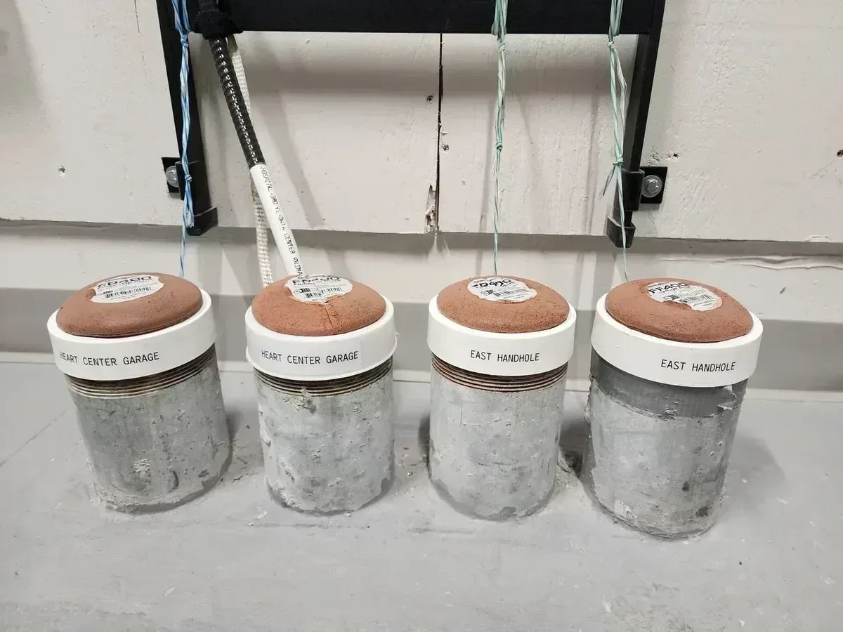
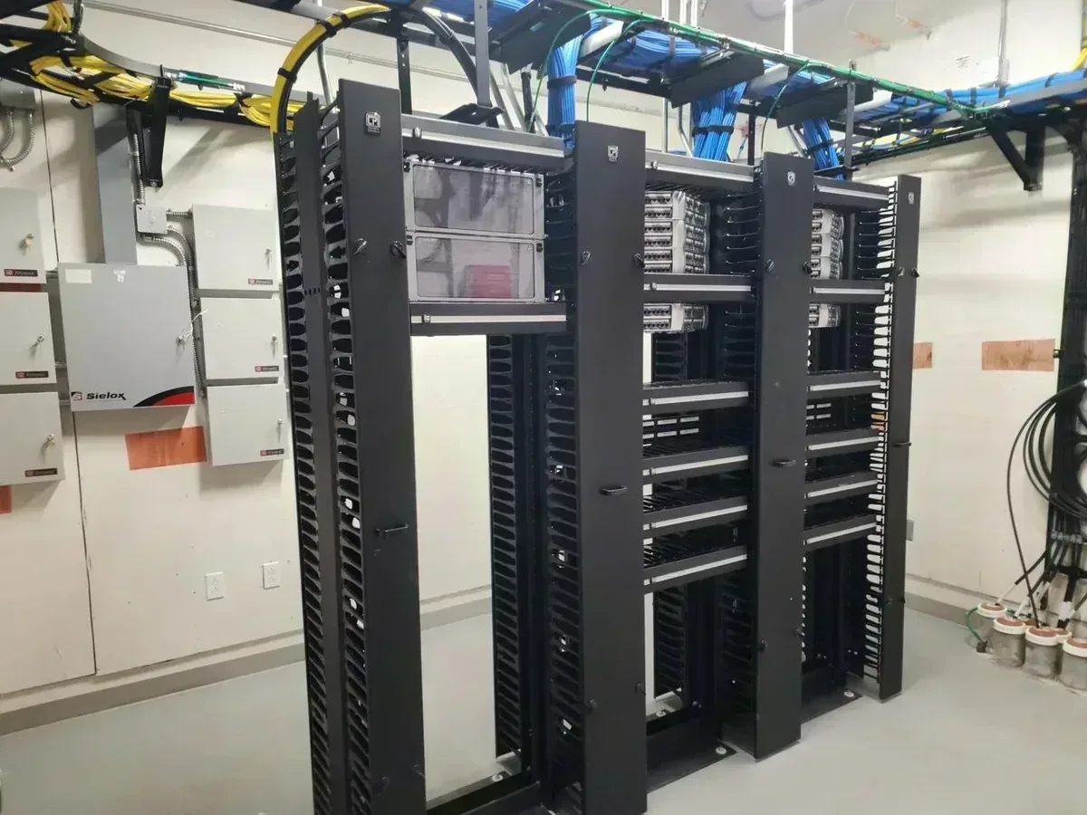
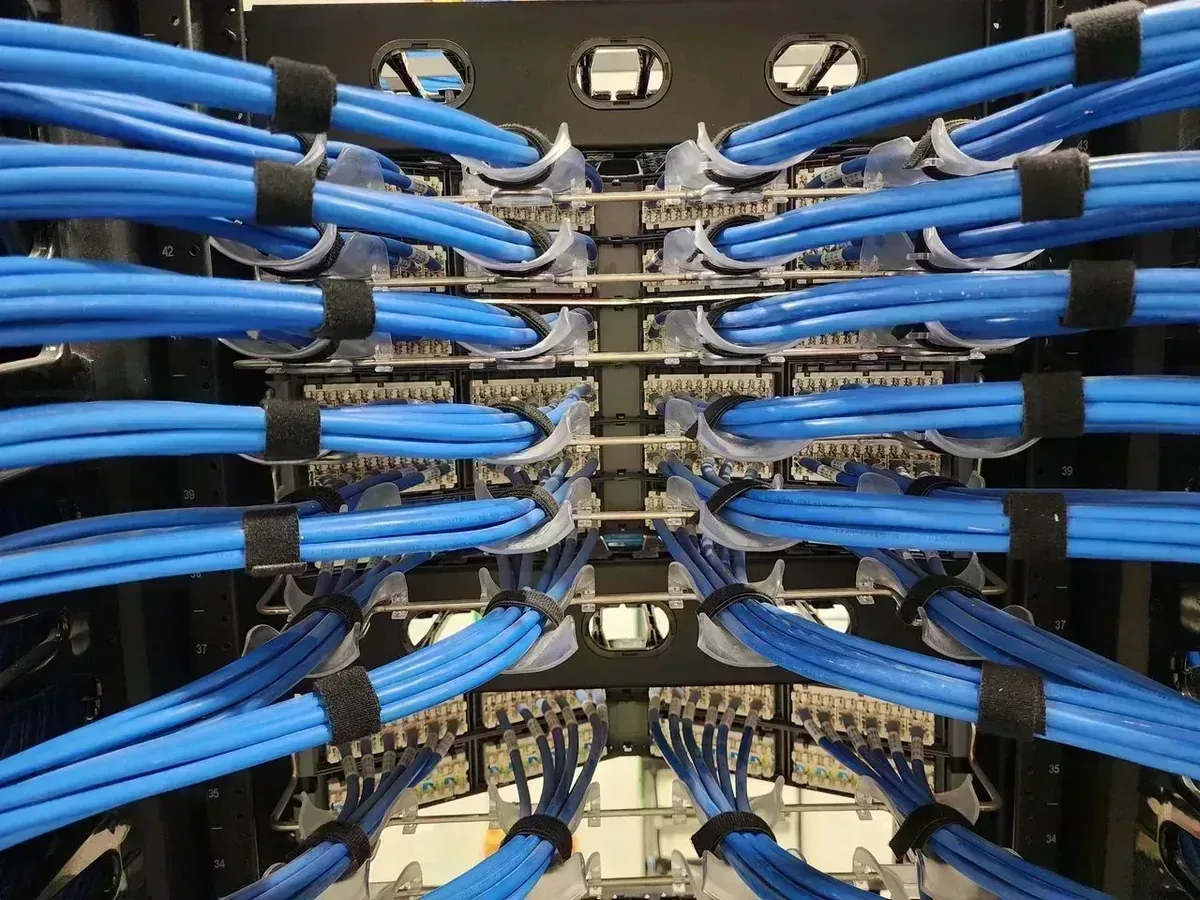
Before punching down, relabel any cables if pulling labels got trimmed. Plan how each cable enters the panel so you can route it cleanly and tie it off later with Velcro or a rear strain relief.
c. Strain Relief & Slack
Zero strain on terminations is crucial. Use cable managers or bracket clips to relieve tension. Plan for service loops that allow future reterminations, but don't overload the back of your rack.
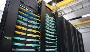
3. Best Practices for Copper Termination
a. Follow the Right Pinout Standard
Confirm whether your job requires T568A or T568B pinout. Don't guess. Most US installs use T568B unless specified otherwise.
b. Use the Proper Tools
High-quality impact punchdown tools are non-negotiable. Avoid cheap or screwdriver-style equivalents. They don't seat connections properly. Keep punchdown blades sharp and clean; dull tools or debris lead to poor terminations and contact failures.
c. Ensure Full Seating & Contact
Termination points must be fully seated into IDC slots. Over-punching can crack terminals; under-punching causes unreliable contact. Aim for a crisp, clean mechanical connection.
d. Maintain Pair Twist
Untwist each pair only as much as necessary (≤½ inch for Cat6). Exceeding specs can cause NEXT (near-end crosstalk) failures and degrade channel performance. Never re-braid conductors. Pair geometry is engineered for performance.
Top Termination Mistakes to Avoid
4. Shielded Cable Termination
a. Ground and Bond Correctly
If you're terminating shielded cable (F/UTP, U/FTP, S/FTP), ensure the drain wire and shield are properly attached to shielded jacks or patch panels. A floating shield acts like an antenna and degrades performance. Ground shields to the TGB (Telecommunications Grounding Busbar) following TIA-607-D and NEC Article 800.100(b).
b. Use Component-Compatible Methods
Always follow the manufacturer's instructions for folding foil, clamping shields, and connector insertion. Mismatched components (e.g., F/UTP cable into a UTP jack) can cause serious reflection or return loss issues.
5. Field-Terminated Fiber (Assuming All Fiber Is Field-Terminated)
a. Mechanical vs. Fusion Termination
Although mechanical connectors were once the norm, fusion splicing is increasingly favored for field installs, thanks to lower insertion loss, faster testing time, and higher consistency. If your team does multiple fiber jobs per month, investing in a lightweight fusion splicer often results in better results and less kneeling under tables. For a deeper look at the process, see our guide on splicing fiber optic cable.
b. Absolute Cleanliness
Fiber end-faces must be completely clean. Use lint-free wipes, isopropyl alcohol, and a fiber cleaning pen before every termination or mating. Dust and oils are the leading causes of loss and failure.
c. Use the Right Tools
Field termination kits must match your fiber type (LC, SC, multimode or single-mode). Use proper stripping tools, cleavers, and alignment systems. Never improvise.
d. Polish, Inspect & Label
Inspect every connector with a fiber scope. Any scratches, chips, or contamination require re-cleaning or reseating. Label both ends clearly for identification and future troubleshooting.
6. Testing & Certification
a. Certify Copper Properly
Use tools like Fluke DSX CableAnalyzer to test:
- 01Wiremap – checks pin-to-pin continuity and wiring correctness
- 02NEXT (Near-End Crosstalk) – checks for interference between pairs
- 03Return Loss – measures reflections from impedance mismatches
- 04Length, propagation delay & delay skew – ensures channel length compliance and sync between pairs
These tests are required for most manufacturer warranties and are often verified by the client.
b. Fiber Testing
Use OTDR or optical loss test sets (OLTS) to measure insertion loss, reflection, and continuity. Verify that loss is within specified limits. Submit test results as part of project documentation. Understanding the parts of a fiber optic network helps you interpret what each test is validating.
c. Provide Headroom
Quality terminations and materials perform above minimum spec, offering "headroom" that absorbs small environmental changes, installation variances, or future interference.
7. Avoid These Common Mistakes
Here are some of the most frequent termination errors and how to prevent them:
- 01Untwisting pairs too far
- 02Mixing T568A/B on the same run
- 03Using poor-quality or worn tools
- 04No slack/strain relief planning
- 05Overdriving or under-punching IDCs
- 06Forgetting to bond shield properly
- 07Skipping fiber inspection or cleaning
Following these steps, and referencing resources like BICSI's copper termination guide and TIA-568.2-D standards, will save you time and protect your reputation.
8. Wrapping Up: Terminations Are Your Signature
Termination quality is where attention to detail truly shines. Clean and correct terminations translate to fewer errors, higher performance, and better client trust. This is where your standard of professionalism becomes visible and measurable.
Use trusted tools, follow standard best practices, and train your team to treat each termination like craftsmanship, not just a step to be rushed.
Frequently Asked Questions
Frequently Asked Questions
According to Fluke Networks, the most common causes are untwisting pairs too far beyond the ½-inch limit, incorrect pinouts (T568A vs T568B mixup), and poor IDC seating from dull or incorrect punchdown tools. Each of these causes immediate certification failures or intermittent network issues.
TIA-568.2-D Section 6.7 limits untwisting to no more than ½ inch (about 13mm) per pair for Cat6. Exceeding this increases near-end crosstalk (NEXT) and commonly results in failed channel certification. Cat6A has even tighter tolerances in many manufacturer specifications.
Both are valid TIA-568 pinout standards for terminating 8-position RJ45 connectors. They differ in which wire pairs land on pins 1-2 and 3-6. T568B is the more common choice in US commercial installations. The critical rule is consistency — mixing A and B within the same channel creates a wiring fault that certification testers flag immediately.
The drain wire and foil shield must be connected to shielded jacks or patch panels and then bonded to the Telecommunications Grounding Busbar (TGB) following TIA-607-D and NEC Article 800.100(b). A shield that floats (not grounded) acts like an antenna and actually degrades performance instead of improving it.
The industry standard is a Fluke DSX CableAnalyzer or equivalent Level IV tester. It checks wiremap, NEXT, return loss, propagation delay, delay skew, and cable length. These test results are required to claim manufacturer channel warranties and are often submitted to the client as part of project closeout documentation.
Fusion splicing is increasingly preferred for commercial field installs because it produces lower insertion loss (typically under 0.1 dB vs. 0.2–0.5 dB for mechanical connectors), more consistent results, and faster overall testing time. Mechanical connectors are still used for quick repairs or low-budget jobs but are harder to certify to tighter loss budgets.
Use a fiber optic inspection scope or video microscope before every mating. Clean first with a lint-free wipe and 99% isopropyl alcohol or a one-click fiber cleaner pen, then inspect. Dust, oil from fingers, or contamination from a previous connection are the leading causes of insertion loss. Never mate without inspecting — damage can transfer to the other end of the adapter.
At minimum, use an OTDR (Optical Time Domain Reflectometer) or an Optical Loss Test Set (OLTS) to measure insertion loss and reflectance. OLTS gives you a bidirectional loss measurement which is required for Tier 1 certification per TIA-526-14. OTDR adds distance-based fault location and event analysis for Tier 2 certification.
Need Structured Cabling in Tampa Bay?
TSS USA installs Cat6 and Cat6A in commercial offices, warehouses, and medical facilities across Tampa Bay. Licensed, permitted, and documented.
Request a Cabling Quote